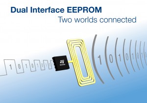
The M24LR64 is an electrically-erasable memory (EEPROM) that can also be programmed wirelessly by industry standard RFID (radio-frequency ID) equipment. Using the M24LR64 for program or data storage provides extra flexibility for customers, allowing software updates or specific parameters to be applied in the supply chain.
With an easy implementation based on two industry standard protocols, I2C and ISO 15693, the dual interface opens new horizons for a wide range of applications for all segments. It enables EEPROM customers now to access their data from outside the application using a passive RF interface.
The link between two worlds
The ability to program or read a memory wirelessly, as well as electrically, enables designers to imagine new concepts and types of product offering.
Dual compatibility makes it an ideal choice for applications needing constant innovation including:
- computers
- consumer electronics
- automotive systems
- medical equipment
- industrial equipment
Key features
- Industry standard interfaces : I2C and ISO/IEC 15693
- 64-Kbit EEPROM user memory
- 64-bit unique identifier (UID, read-only)
- Write protection in I2C access with 32-bit password
- Write/read protection in RF access with 32-bit password
- Application family identifier (AFI)
- Data storage format identifier (DSFID)
- 13.56 MHz carrier frequency
Key benefits
- State-of-the-art EEPROM technology
- Most flexible solution for parameter updates
- High reliability
- Simple and cost-effective implementation
- Fits with a very wide range of inlay sizes
- ISO/IEC 15693 compliance allows use of large off-the-shelf readers base
- A new way for:
- calibration
- activation
- parameter update
- diagnostics
- traceability
- asset tracking
- identification
even when application is turned off
With considerable experience in the EEPROM and RFID domains, as well as partnerships with system integrators and involvement in standardization committees, ST gives its customers a leading-edge flexibility in their applications. The M24LR64 offers a simple and cost-effective implementation; with a 13.56 MHz inductive antenna and without adding extra components.
Hardware considerations
Pinout comparison
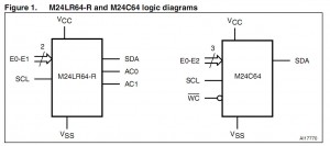
Figure1 and Figure2 show the logic diagrams and the pinouts of the M24LR64-R and M24C64 devices, respectively.
M24LR64-R AC0/AC1 pins: due to its RF capability, the M24LR64-R dual interface EEPROM features two inputs (AC0 and AC1) to connect the RF antenna.
Consequently, two inputs present in the M24C64 are not offered in the M24LR64-R: these are E2 and Write Control (WC). Practically, this means that you will be able to use up to four M24LR64-R devices (defined by E0, E1) on the same I²C bus, compared to eight devices (defined by E0, E1, E2) for the M24C64. The Write Control input (WC) is used to write-protect the M24C64. The M24LR64-R can also be protected but in a different way, using the I2C_Write_Lock bits.
Figure2 shows that the four mandatory pins for the I²C bus (VSS, VCC, SCL, SDA) are positioned likewise in the two devices. AC0 and AC1 are connected to pin 2 and pin 3, respectively. They have to be next to each other for RF capability requirements. As a result, E1 was moved to pin 7 in the M24LR64-R, whereas it is connected to pin 2 in the M24C64.


