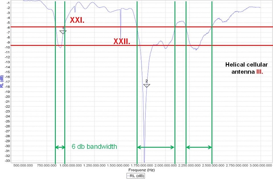
Once more you will detect the typical faults marked with XXI and XXII. The bandwidth for the lower GSM bands is very small and the triangle marker 1 for the middle of the GSM 900 band is on the right side of the gap. There is a need for a matching circuit for sure. For the higher GSM bands up the UMTS 2100 the antenna looks good. If it will be used for GSM 1800 or GSM 1900 only, then a return loss of 9.5 dB can maybe archived in the final design. For some reasons this antenna shows a resonance at 2400 MHz range as well.
The upper text is out of the IoT M2M Cookbook here. If you are interested in a copy of the book please do not hesitate to drop an email to harald.naumann (at) gsm-modem.de
Remark: The first low budget VNA had a to noisy output. The Smith Chart diagram contained to many loops and at UMTS 2100 and LTE 2700 the noise made the diagram close to unusable. I replaced it to a profesional VNA listed here.

