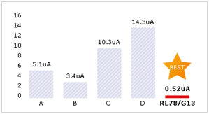
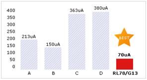
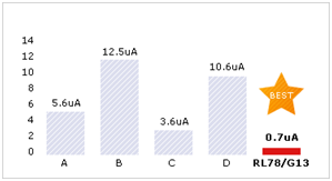
The power consumption is from nearly 1 uA to 480 mA in average. The 1 uA we get if we create an asset tracker behind oil on canvas. The asset tracker will wait for an event all the time. The 480 mA we get by GPRS class 10 in GSM power level with TX output power of 2 Watt.
1 uA during stop mode
If you design your application right, then the self discharge of the battery is already higher. Ultra low power micro controllers like Renesas RL78 charge you 70 uA per MHz and 0.52 uA in stop mode.

RL78 with 0.52 uA with in stop mode
1.5 mA for GPRS module in idle mode
In idle mode the module is able to receive a SMS or an incoming call (voice, CSD or fax), but is not able to receive IP communication by GPRS.
20 mA during GPRS
During GPRS in receiving mode the power consumption is 20 mA.
250 mA during transmission
Fax, voice, data and GPRS in class 8 will charge up to 250 mA in average in highest power level in GSM 850/900
480 mA during transmission
In GPRS class 10, the GPRS module is transmitting faster. This doubles the average TX current. The average will be up to 480 mA.
1 Ampere
In GSM 1800 and GSM 1900 the peak current is up to 1 Ampere. GSM / GPRS is transmitting in bursts.
1.8 Ampere
In GSM 850 and 900 the peak current is up to 1.8 Ampere ( maybe 2 Ampere). Your battery or power supply or the better sad your supply voltage concept shall be able to drive 2 Ampere peaks. This peaks you can get by SMS or by handover between base stations too. Take care on the impedance of batteries. Anyhow, the selection of right power supply is a new difficult story.
More than 2 Ampere
Some GSM modules try to optimise poor antennas by raising the power higher than 2 Watt! Take care on good GSM antennas. Poor antennas will raise the average power consumption even when the GSM module will not transmit with more than 2 Watt. If the loss in the GSM antenna is too high, then the GSM base station will ask the module for more power. Poor antennas can discharge your batteries faster.
1 uA to 2 Ampere
Everything in between is possible. Just compare with your mobile phone on your desktop and the same phone moving in your car. The hand over between the base stations during the trip will raise the average power consumption.
58 mW with GPS
58 mW / 3.8 Volt = 15 mA. Or 70 mA /3.8 Volt = 18.4 mA. Important is to reduce the time for first fix. Our free of charge A-GPS server will help to reduce power. A-GPS minimise the time for first fix.
500 uA for SirfAware
SirfAware loads the emphasis data and synchronise the RTC in background. It discharge the battery with 500 uA in average. It is a nice feature if you connect the GPS position often, but it is useless for tracking oil on canvas.
150 mW with GPS/Glonass
More power is maybe better. Our combined GPS/Glonass module charge more current if it tracks more channels. In Paris we were able to receive 21 channels in parallel. Anyhow, worst case you see 3 GPS and 1 Glonass, 2 GPS and 2 Glonass, 1 GPS and 3 Glonass or 0 GPS and 4 Glonass satellites on the sky. Without Glonass you will not be able to locate anything. A good example was the Iraq war. Rumours tell that we got 5 hours nothing.
The selection of the right GPS module with the right A-GPS concept and the right power save mode is a decision that will change the power consumption and the stand by time of your device dramatic. Is a single GNSS module that supports GPS only enough or is it better to use a hybrid GPS/Glonass module? Makes it sense to use A-GPS? Is the using of 1-axis gyro, 3-axis gyro, accelerometer, pressure sensor, magnetometer and Odometer interface useful or not? Makes it sense to develop a prototype with 1-axis gyro, 3-axis gyro, accelerometer, pressure sensor, magnetometer and Odometer interface and after test to decide which sensors will help to get best indoor positioning. Will one of the five different power save modes helpful and which out of five to select? A-GPS by A-GPS-server, self assisted A-GPS or A-GPS on demand? Directional GPS patch antennas with right hand polarisation, non polarised GPS chip antennas, single ended GPS helical antennas or better to select a ground plan independent helical with balun to minimise the effect of human body. Shall we trust one GNSS system like GPS or is it saver to use a hybrid GPS/Glonass module?
If you have answered the upper questions on GNSS module, then you just have to answer similar question for the GSM / GPRS module. Is GSM enough? Is GPRS necessary? Is SMS enough? Is USSD maybe to best option to save power? Will an unidirectional GSM antenna the best or is it better to force some direction by using PIFA antennas? How to pass SAR? How to pass Europian RTTE, American FCC or American PTCRB? What about Australian Atec or Brazilian Anatel?
Nevertheless, we will be glad to share our more than 15 years in GSM and GPS plus 25 years in radio communication with you. Just send an e-mail to harald.naumann@gsm-modem.de or use the form here.


Hi
I am working on a chip antenna for GPS module. I have to determine the trace width between antenna and GPS module. This depends on current and power consumption, it was not provided for this GPS reciever, Should I assume its 150mW on average? and so what should be current drawn?
Regards
State of the art GPS modules already offer less than 150 mW. Any 150 mW / 3 Volt = 50 mA.
hi i need very less current consumption gsm module , which one should i select ,please guide me. i am working with 1300 mAh buttery, but gsm Board is not supporting so please help me . its very important .
A battery with 1300 mAh will hopefully offer you a low impedance. The GSM module will charge up to 2 Ampere peak current.
5 Supply voltage 14
5.1 Power on timing and waiting (14.04.14) 14
5.2 Cellular module in power save mode (14.04.2014) 14
5.3 Internal resistance of batteries and linear voltage transformers 15
5.4 Switched mode voltage regulator 17
5.5 Simulation of a switched power supplies with LT Spice 17
5.6 Capacitors at power supply and cellular module 19
Read more http://www.gsm-modem.de/M2M/m2m_iot_cookbook/
5.7 Supply voltage for GNSS antenna 19